Robot Calibration with TCP Measuring Instruments
What is a Tool Center Point (TCP)?
To describe a tool in robotics, a coordinate reference system called Tool Center Point (TCP) is used. The TCP defines the position and orientation of the tool tip relative to the robot's flange (see Figure 1). The tool coordinates can be entered either directly from CAD data or measured with a calibration method.
When programming an application, the tool's coordinate system should be used for all motion commands. If the tool changes, the TCP is simply updated — this change automatically applies to all of the robot's motion programs where this tool is used.
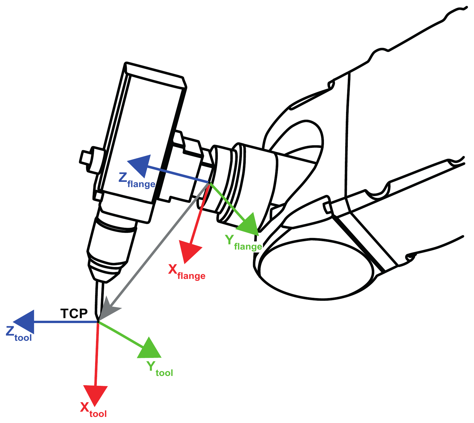
Figure 1: Tool coordinate system (TCP) relative to the robot's flange coordinate system
Why Automatic TCP Calibration?
State-of-the-art robotic automation systems rely on high accuracy. In many applications — such as dispensing, welding, or laser cutting — tool changes are permanently ongoing due to wear, bending, or replacement in harsh environments. Since these applications often require the highest possible accuracy, it is necessary to check and recalibrate the TCP on a regular basis.
Common triggers for recalibration include:
- Tool replacement or tip change
- Collision or unexpected impact
- Beginning of a work shift
- After maintenance
- After every N process cycles (application-dependent)
Manual recalibration (e.g. the traditional 4-point method on a spike) takes 10 or more minutes per tool and is subject to operator variability. Automatic recalibration with a TCP measuring instrument takes only a few seconds, eliminates human error, and can run without operator intervention — reducing downtime and increasing quality.
CAPTRON TCP Measuring Instruments
CAPTRON offers high-precision TCP measuring instruments designed for automatic tool verification and recalibration in industrial robot cells. Key features:
| Feature | Specification |
|---|---|
| Measurement principle | Two perpendicular laser light barriers |
| Reproducibility | 0.01 mm |
| Switching frequency | Up to 10 kHz |
| Detectable objects | Metallic and non-metallic |
| Aperture sizes | 40 mm and 70 mm (depending on model) |
| Output signals | Digital switching signals (NPN/PNP) |
The instruments are available as ring-type (enclosed aperture) and open-frame variants. For Universal Robots, a dedicated URCap software plugin is available that handles the complete measurement and correction sequence within the robot program.
Setup Requirements
Before performing TCP calibration, ensure the following:
- Rigid mounting: The TCP measuring instrument must be securely mounted on a vibration-free surface within the robot's work envelope. The instrument must not shift between reference and recalibration runs.
- Tool mounting: The tool must be firmly attached to the robot flange with no play or wobble. Even slight looseness introduces inconsistent errors.
- Aperture clearance: The tool tip must pass through the laser beams without the tool holder or other parts blocking the beam. Choose an aperture size (40 mm or 70 mm) that provides sufficient clearance for the tool geometry.
- Wiring: Connect the instrument's switching outputs to the robot controller's digital inputs. For best accuracy, use fast measurement inputs rather than standard I/O (see Speed and Accuracy).
- Path programming: Program a circular (or square) horizontal path that passes through both laser beams twice per revolution. The path radius should keep the tool within the aperture throughout the movement.
Measurement Principle
The CAPTRON TCP measuring instrument uses two perpendicular laser light barriers (X-beam and Y-beam) to determine the tool position.
Since the tool has a diameter greater than zero, the laser beam is interrupted for the entire travel of the tool through the beam. The center of the interruption — calculated from the robot positions at the falling edge (beam interrupted) and rising edge (beam restored) — gives the tool reference point:
x_center = (x_falling_edge + x_rising_edge) / 2
The robot controller captures its TCP position at the instant of each signal transition. The accuracy of this position capture depends on the switching frequency of the sensor and the speed of the robot controller's inputs (see Speed and Accuracy).
The duration of the beam interruption also encodes the tool diameter: d_tool = v_robot x t_interruption. This can be used to detect tool wear (a worn tip has a smaller diameter) or to verify that the correct tool is mounted.
Calibration Procedure
Initial Reference Run
The reference run is performed once during setup (and repeated whenever the instrument is repositioned or a new tool type is installed).
- Mount the tool on the robot flange and the TCP measuring instrument in its fixed position.
- Move the robot arm on a circular horizontal path through the TCP measuring instrument at height z_1. Each laser beam (X and Y) should be interrupted twice per revolution.
- For each beam, calculate the center of each interruption from the falling and rising edges. This yields two reference positions per axis: x_ref1, x_ref2 and y_ref1, y_ref2.
- Calculate the averaged reference positions:
x_ref = (x_ref1 + x_ref2) / 2
y_ref = (y_ref1 + y_ref2) / 2
- Store x_ref and y_ref in the robot controller as the baseline reference values.
- Verification: Move the tool to the center point of the instrument where both laser beams cross. Both beams should be interrupted simultaneously. If not, repeat the reference run.
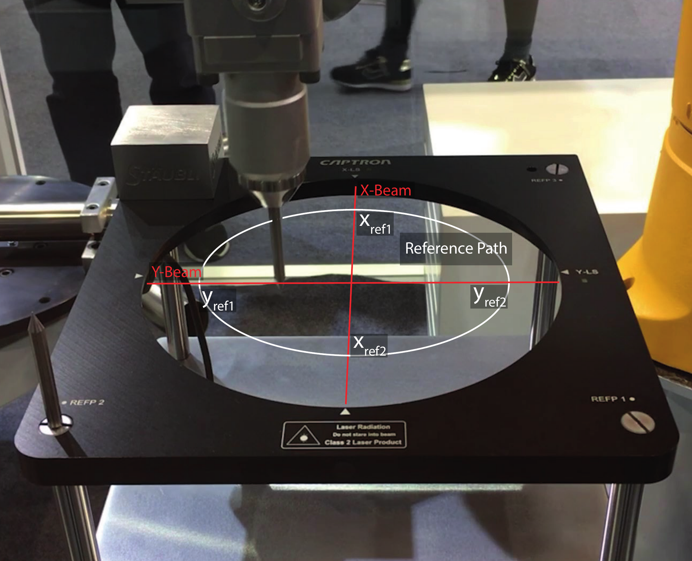
Figure 2: TCP reference measurement — the tool follows a circular reference path through the X-beam and Y-beam, generating two reference positions per axis
Recalibration Run
The recalibration run is executed automatically whenever a tool check or correction is needed.
- The robot moves to the TCP measuring instrument and executes the same circular path as the reference run.
- Record the new positions: x_cal1, x_cal2 and y_cal1, y_cal2.
- Calculate the current averaged positions:
x_cal = (x_cal1 + x_cal2) / 2
y_cal = (y_cal1 + y_cal2) / 2
- Compute the deviations from the reference:
Δx = x_cal - x_ref
Δy = y_cal - y_ref
- Apply the corrections to the TCP coordinates in the robot controller:
TCP_x_new = TCP_x_current + Δx
TCP_y_new = TCP_y_current + Δy
- Verification: Optionally, move to the beam crossing point to confirm both beams are interrupted simultaneously, validating the correction.
If the deviations exceed a defined threshold (e.g. several millimeters), this may indicate a collision, broken tool, or incorrect tool mounted. In this case, the robot program should halt and alert the operator rather than blindly applying the correction.
Tilt Correction
A pure X/Y correction adjusts the tool position but does not account for angular errors. A bent welding tip, for example, may have shifted at the tip while the mounting point at the flange remains unchanged. For long tools, even a small tilt angle translates to significant positional errors at varying Z heights.
To detect and correct tilt, two calibration runs are performed at different heights z_1 and z_2 (see Figure 3):
- Perform a calibration run at height z_1 → yields deviations (x_cal1, y_cal1).
- Perform a calibration run at height z_2 → yields deviations (x_cal2, y_cal2).
- Calculate the tilt angles:
α_x = arctan((x_cal2 - x_cal1) / (z_2 - z_1))
α_y = arctan((y_cal2 - y_cal1) / (z_2 - z_1))
- Apply the angular corrections to the TCP orientation (A, B, C or Rx, Ry, Rz depending on the robot brand).
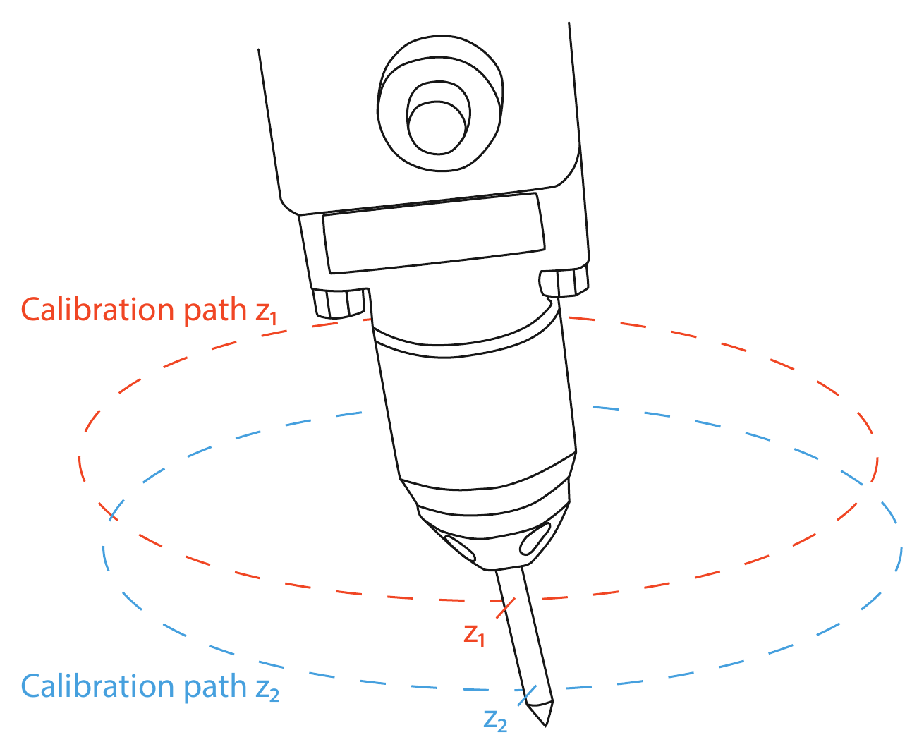
Figure 3: Tilt correction calibration path — two circular paths at heights z_1 and z_2 reveal the tilt angle of a bent tool
Worked example: A welding tip that has shifted 0.5 mm in X between z_1 and z_2 separated by 50 mm results in a tilt angle of arctan(0.5 / 50) = 0.57°. While this angle seems small, at a working distance of 200 mm from the flange, it produces a 2.0 mm positional error at the tip — far outside typical welding tolerances.
Speed and Accuracy
The accuracy of TCP measurement depends directly on how fast the robot controller can capture its position at the moment the laser beam is interrupted. The fundamental relationship is:
position_error = v_robot x (t_sensor + t_input)
Where v_robot is the TCP velocity during measurement, t_sensor is the sensor response time, and t_input is the robot controller's input scan time.
| Robot Speed | Standard Input (12 ms) | Fast Input (0.1 ms) |
|---|---|---|
| 10 mm/s | 0.12 mm | 0.001 mm |
| 50 mm/s | 0.60 mm | 0.005 mm |
| 100 mm/s | 1.20 mm | 0.010 mm |
| 200 mm/s | 2.40 mm | 0.020 mm |
CAPTRON TCP instruments switch at up to 10 kHz (0.1 ms response time), enabling high accuracy even at elevated robot speeds. However, this advantage is lost if the robot controller uses slow standard digital inputs.
Standard digital inputs (5-12 ms scan cycle) produce unacceptable measurement errors at typical robot speeds. Always use the fastest available input type on your robot controller — for example, KUKA $MEAS_PULSE fast measurement inputs (125 μs) or equivalent position-capture inputs on other brands.
Practical guideline: For a target accuracy of 0.01 mm with CAPTRON instruments and fast measurement inputs, robot speeds of up to 80 mm/s are achievable. With standard inputs, the robot would need to move below 1 mm/s to reach the same accuracy — making the measurement impractically slow.
When to Recalibrate
The optimal recalibration frequency depends on the application, tolerance requirements, and environmental conditions. Use the following guidelines as a starting point:
| Application | Typical Tolerance | Recommended Frequency |
|---|---|---|
| Laser cutting / precision assembly | < 0.05 mm | Every cycle or every N parts |
| Dispensing / gluing | < 0.1 mm | Before each process cycle |
| Arc welding | < 0.5 mm | After each tip change / every shift |
| Spot welding | 0.5 - 1.0 mm | Every shift or daily |
| General handling | > 1.0 mm | Weekly to monthly |
In addition, always recalibrate after:
- Any tool change or tip replacement
- A collision or unexpected impact
- Maintenance on the robot or tool
- Extended downtime (thermal conditions may have changed)
- Quality inspection detects drift or rejects
Since automatic recalibration with a CAPTRON instrument takes only a few seconds, it is often practical to verify the TCP more frequently than strictly necessary — the cost of checking is minimal compared to the cost of producing scrap parts.
Robot Controller Integration
The CAPTRON TCP measuring instrument outputs digital switching signals that indicate when the laser beam is interrupted. These signals must be connected to the robot controller and processed by the robot program.
General signal chain:
- Tool enters laser beam → instrument output switches (falling edge)
- Robot controller captures its current TCP position at the signal transition
- Tool exits laser beam → instrument output switches back (rising edge)
- Robot controller captures position again
- Robot program calculates center position and applies correction
Input type recommendations by robot brand:
| Robot Brand | Recommended Input Type |
|---|---|
| KUKA | $MEAS_PULSE fast measurement inputs (125 μs) |
| FANUC | Position-capture digital inputs |
| ABB | Fast digital inputs or EGM interface |
| Universal Robots | CAPTRON URCap plugin (handles measurement automatically) |
| Yaskawa | High-speed digital inputs |
For Universal Robots, the CAPTRON URCap plugin provides a complete integration: step-by-step setup, automatic measurement, and TCP correction — all within the Polyscope programming environment. The URCap supports all UR e-Series and newer models.
For PLC-integrated cells, the PLC typically orchestrates the calibration sequence: it triggers the robot to move to the measurement station, monitors the calibration result, and authorizes resumption of production. The CAPTRON instrument's switching signals can also be routed through the PLC if the robot controller does not have sufficiently fast direct inputs.
If you have questions about our products and the integration into your processes, please contact us at pdm@captron.com.