CANEO series10 + Allen-Bradley — Add-On Instruction Guide
This guide walks through integrating a CANEO series10 button with an Allen-Bradley ControlLogix or CompactLogix controller in Studio 5000 Logix Designer. By the end you'll be reading the button's state from ladder logic and writing LED scenes or RGB colors to it — all through a CAPTRON Add-On Instruction (AOI) that hides the byte-level plumbing.
Most IO-Link masters on EtherNet/IP hand the controller its process data as one flat SINT array covering every port on the block. Some CANEO series10 fields, such as the actuation count, are larger than one byte, and some masters also swap the byte order. The AOI takes care of both: you point it at the master's raw arrays and tell it where your port starts, and it gives you back two clean, named structures to read and write.
Prerequisites
Before starting, make sure:
- Studio 5000 Logix Designer is installed and you have a project open for your controller. This example uses a 5069-L306ER CompactLogix on firmware v38.
- An IO-Link master is configured under I/O Configuration and its input and output data are visible as controller tags. This example uses a MURR IMPACT67 Pro E DIO8 IOL8 M12L 5P (54631).
- The CANEO series10 is wired to an IO-Link port on the master (this example uses port 1).
- You have downloaded
CANEOseries10_V34_AOI.zipand unzipped it to get the two AOI files (see Download at the end of this guide). - You have the CANEO series10 process data layout handy for the meaning of each value: series10 Process Data.
Choose the LED control mode
The series10 only uses the output process data you send it if the button is set to accept it. This is the IO-Link parameter LED Control Mode, which you'll find in the IODD under LEDs → LED Control Mode:
| LED Control Mode | What the button shows | AOI to use |
|---|---|---|
Automatic Scene selection | Scenes are selected by the button's own triggers. The output process data is unused. | — |
Scene controlled by IO-Link Process Data | The LED shows one of the eight scenes configured in the IODD. You pick the scene from the PLC. | AOI_CANEOseries10_Scene_Control_V34 |
Advanced control by IO-Link Process Data | The PLC sets the LED directly: on/off, RGB color, effect, and brightness. | AOI_CANEOseries10_Advanced_Control_v34 |
Classic Two LED Mode | The LED is driven by the input pins. The output process data is unused. | — |
Scene control covers most applications. Use Advanced control when eight scenes aren't enough and you want to set the LED color from the PLC. For details on each mode, see series10 LED Control.
Pick one AOI per button. The two AOIs share the same input structure, but their output structures are different and match only their own LED Control Mode. Set the LED Control Mode on the button first, then use the matching AOI.
1. Import the Add-On Instructions
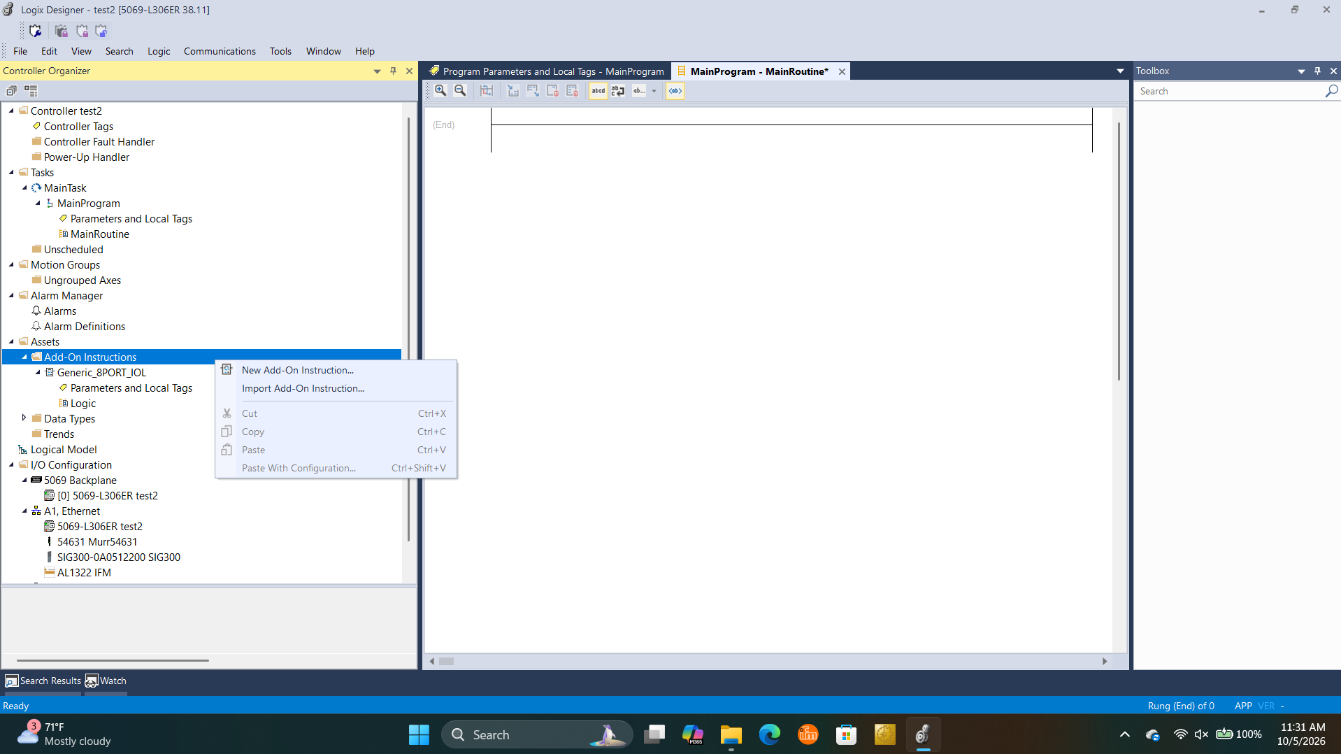
In the Controller Organizer, expand Assets, then right-click Add-On Instructions and choose Import Add-On Instruction….
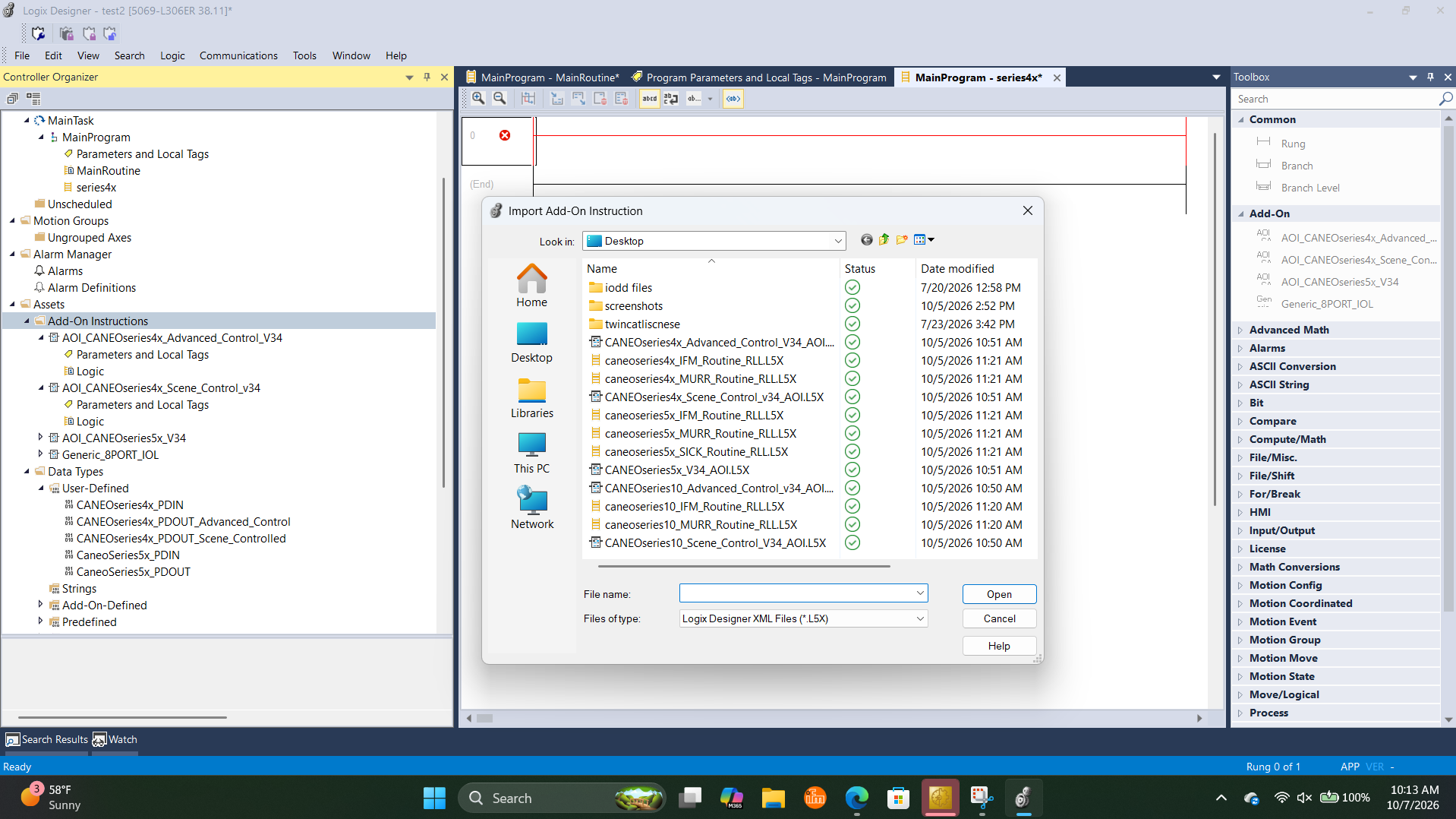
Browse to the unzipped files and import CANEOseries10_Scene_Control_V34_AOI.L5X, CANEOseries10_Advanced_Control_v34_AOI.L5X, or both. Confirm the import dialog that follows.
After the import, the AOIs appear under Add-On Instructions, and their user-defined data types (UDTs) appear under Data Types → User-Defined:
CANEOseries10_PDIN— the process data coming from the button. Used by both AOIs.CANEOseries10_PDOUT_Scene_Controlled— the process data going to the button in Scene control mode.CANEOseries10_PDOUT_Advanced_Control— the process data going to the button in Advanced control mode.
2. AOI parameters
Open the AOI definition and switch to the Parameters tab to see what the instruction expects. Both AOIs have the same parameters — only the data type of IOL_PD_OUT differs.
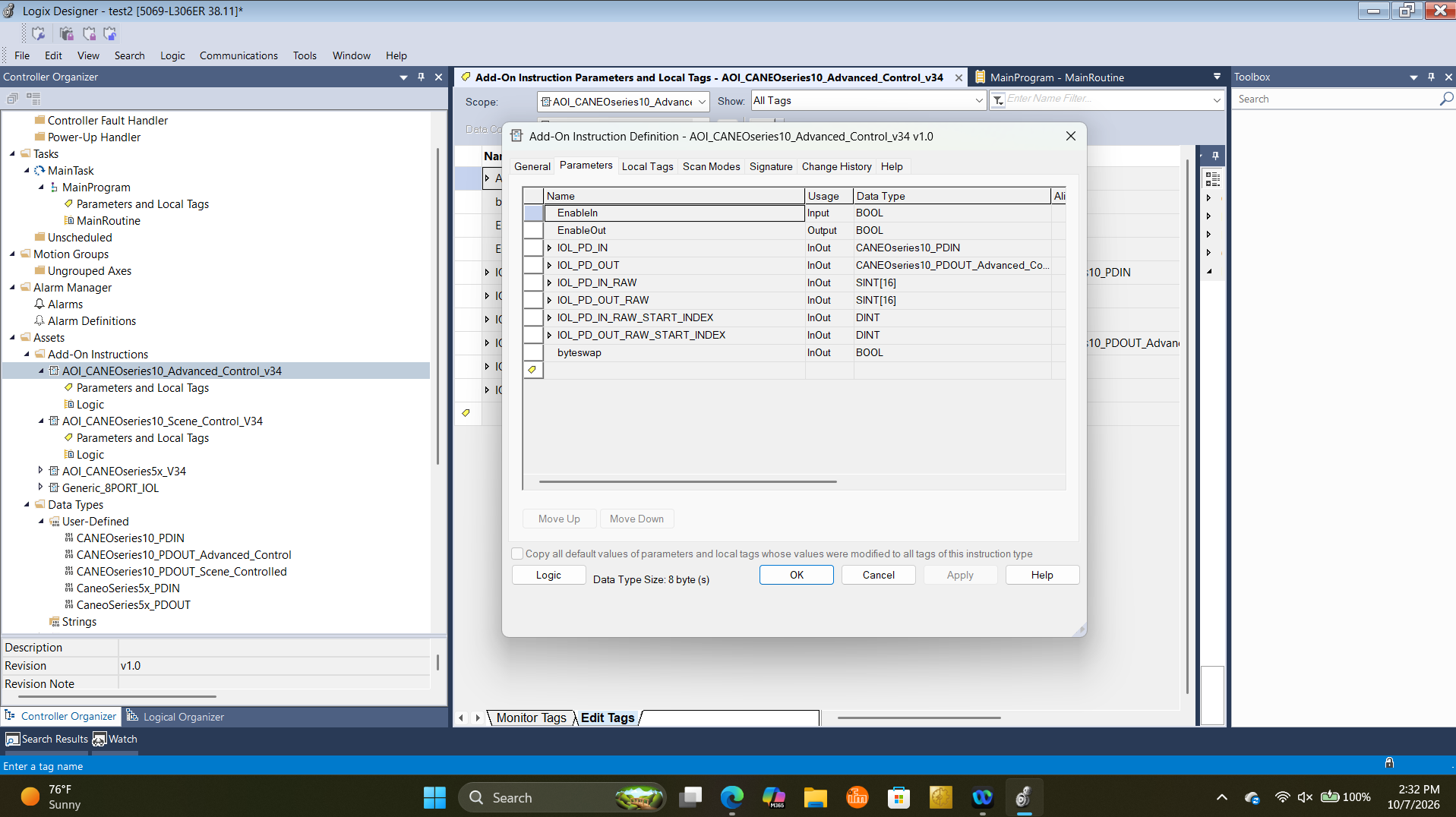
| Parameter | Data type | Description |
|---|---|---|
IOL_PD_IN | CANEOseries10_PDIN | Structure the AOI fills with the CANEO series10 input process data. Read the button's state from here. See Reading the button. |
IOL_PD_OUT | CANEOseries10_PDOUT_Scene_Controlled or CANEOseries10_PDOUT_Advanced_Control | Structure you write to. The AOI packs it into the output process data. See Scene control and Advanced control. |
IOL_PD_IN_RAW | SINT[16] | The raw IO-Link input process data array from the IO-Link master (as defined by the master's EDS file). |
IOL_PD_OUT_RAW | SINT[16] | The raw IO-Link output process data array from the IO-Link master (as defined by the master's EDS file). |
IOL_PD_IN_RAW_START_INDEX | DINT | Index of the first input byte of the port the CANEO series10 is connected to. Consult your IO-Link master's manual for the byte layout. |
IOL_PD_OUT_RAW_START_INDEX | DINT | Index of the first output byte of the port the CANEO series10 is connected to. Consult your IO-Link master's manual for the byte layout. |
byteswap | BOOL | Set to 1 if your IO-Link master swaps the byte order of the process data. Default is 0 (no swap). |
Do I need byte swapping? IO-Link masters don't all format process data the same way. Some present each 16-bit word with its two bytes swapped. Masters from Turck, IFM, and Comtrol commonly do this. If the LED colors come out mixed up, or values like the actuation count look wrong, set
byteswapto1.
3. Add the AOI to your routine
Open your routine (here MainProgram → series10) and add the AOI that matches your LED Control Mode to a rung — you'll find both in the Toolbox under Add-On. Every operand starts as a question mark.
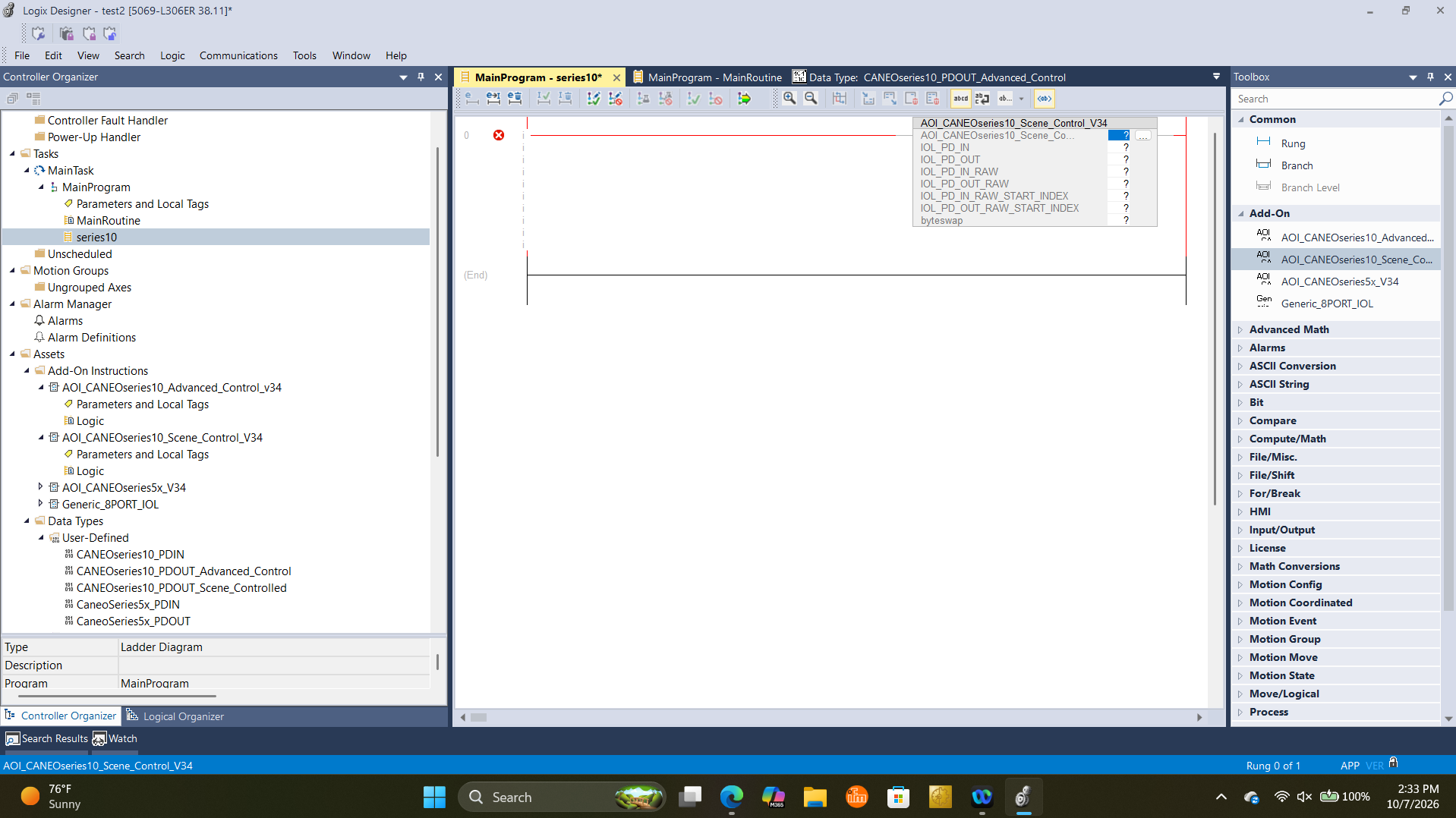
Fill in the operands one by one. For the tags that don't exist yet, right-click the question mark and choose New Tag:
- AOI instance — create a new tag of the AOI's type (e.g.
AOI_port1_MURR). Use one instance per button. IOL_PD_IN— create a new tag of typeCANEOseries10_PDIN(e.g.CS10_PDIN_port1).IOL_PD_OUT— create a new tag of the matching output type (e.g.CS10_PDOUT_port1of typeCANEOseries10_PDOUT_Scene_Controlled).IOL_PD_IN_RAW/IOL_PD_OUT_RAW— select the IO-Link master's input and output data arrays from the Controller Tags.IOL_PD_IN_RAW_START_INDEX/IOL_PD_OUT_RAW_START_INDEX— enter the index of the first input and output byte of the port the CANEO series10 is connected to. These values are specific to your IO-Link master. If your master (or the master manufacturer's own AOI) already gives you a separate array per port, the start index is most likely0— see Using integer arrays.byteswap—0or1, depending on your master (see above).
Example: MURR IMPACT67 (54631), port 1
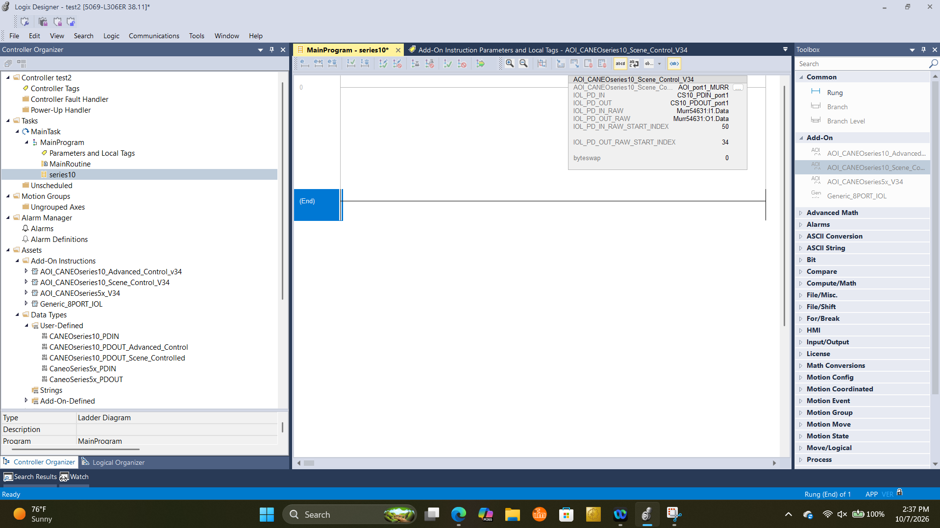
| Operand | Value | Why |
|---|---|---|
| AOI instance | AOI_port1_MURR | Named after the port and the master it serves. |
IOL_PD_IN | CS10_PDIN_port1 | Named after the product (CS10), the type of process data, and the port. |
IOL_PD_OUT | CS10_PDOUT_port1 | Same naming scheme for the output side. |
IOL_PD_IN_RAW | Murr54631:I1.Data | The MURR block's complete input data array, stored under Controller Tags. |
IOL_PD_OUT_RAW | Murr54631:O1.Data | The MURR block's complete output data array. |
IOL_PD_IN_RAW_START_INDEX | 50 | First input byte of port 1 in the MURR input array. |
IOL_PD_OUT_RAW_START_INDEX | 34 | First output byte of port 1 in the MURR output array. |
byteswap | 0 | The MURR block does not swap bytes. |
In this example the entire MURR data array is passed in, and the start indexes tell the AOI where port 1's data begins inside it. To connect a button on another port, add a second AOI instance with its own PDIN/PDOUT tags and that port's start indexes.
4. IOL_PD_IN — reading the button
CANEOseries10_PDIN is the same for both AOIs. It holds the button's actuation state, its pin states, and its sensor readings.
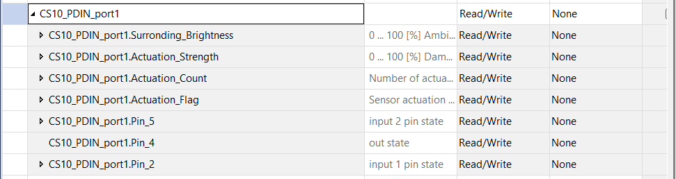
| Member | Data type | Description |
|---|---|---|
Surronding_Brightness | SINT | Ambient brightness measured by the button's light sensor, in percent (0…100). |
Actuation_Strength | SINT | Damping of the sensor, in percent (0…100). |
Actuation_Count | INT | Number of actuations since the button was powered on. Resets on restart and after 65535. |
Actuation_Flag | SINT | Sensor actuation state: 0 = idle, 1 = actuated. |
Pin_5 | SINT | Input 2 (E2) pin state: 4 = input off, 5 = input on, 8 = pin unused. |
Pin_4 | BOOL | OUT pin state: 0 = output off, 1 = output on. |
Pin_2 | SINT | Input 1 (E1) pin state: 4 = input off, 5 = input on, 8 = pin unused. |
Actuation_Countabove 32767 shows as negative. The button counts up to65535, butINTin Logix is signed. Past32767the tag rolls over to negative values. If you need the full range, copy it into aDINTand add65536when it's negative.
For the full input layout, see series10 Process Data.
5. IOL_PD_OUT — Scene control mode
Use CANEOseries10_PDOUT_Scene_Controlled with AOI_CANEOseries10_Scene_Control_V34 when the LED Control Mode is Scene controlled by IO-Link Process Data.

| Member | Data type | Description |
|---|---|---|
LED_SCENE | SINT | Active LED scene, 0…7. Write -1 (255) to let the button select the scene from its actuation and input pins instead. |
The scenes themselves — color and effect for each of the eight — are configured in the IODD. See series10 LED Scenes.
6. IOL_PD_OUT — Advanced control mode
Use CANEOseries10_PDOUT_Advanced_Control with AOI_CANEOseries10_Advanced_Control_v34 when the LED Control Mode is Advanced control by IO-Link Process Data.
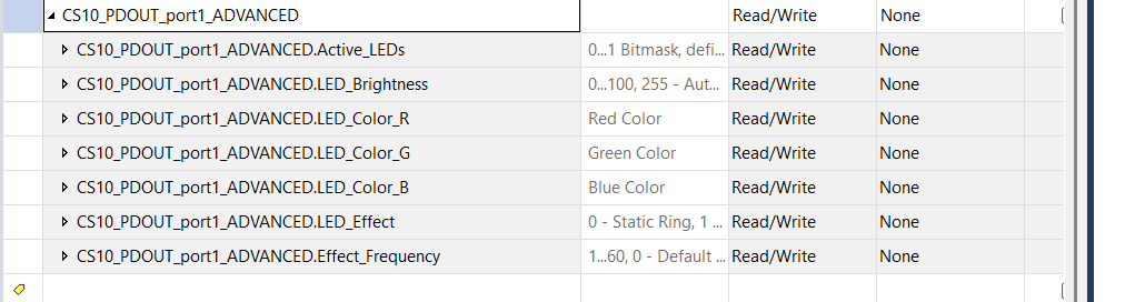
| Member | Data type | Description |
|---|---|---|
Active_LEDs | INT | Turns the LED on or off: 1 = on, 0 = off. |
LED_Brightness | SINT | Brightness of the LED ring in percent (0…100). Write -1 (255) for automatic brightness. |
LED_Color_R | SINT | Red component of the LED color, 0…255. |
LED_Color_G | SINT | Green component of the LED color, 0…255. |
LED_Color_B | SINT | Blue component of the LED color, 0…255. |
LED_Effect | SINT | LED effect: 0 = Static Ring, 1 = Flash Ring, 2 = Pulse Ring. |
Effect_Frequency | SINT | Frequency of the LED effect in 1/10 Hz, 1…60 (0.1…6 Hz). 0 = default frequency. |
Values above 127 are written as negatives.
SINTin Logix is signed (-128…127), but the color and brightness fields take0…255. To send a value above 127, write it minus 256 — for example-1for255(full color or automatic brightness) or-128for128.
7. Usage example — Scene control
The ladder logic below switches LED scenes based on the button's OUT pin.
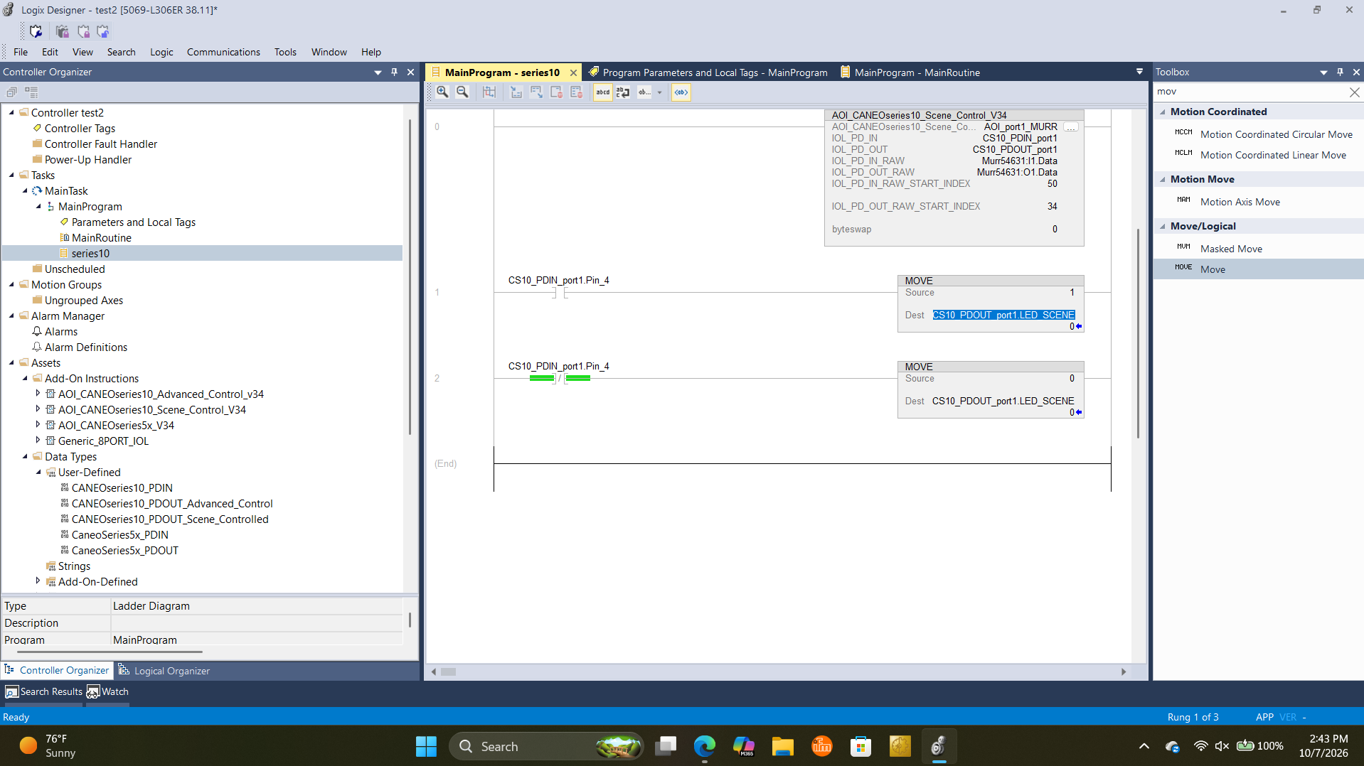
- Rung 0 — calls
AOI_CANEOseries10_Scene_Control_V34. It must be scanned on every cycle, so leave it unconditional. - Rung 1 — while the OUT pin is on (
XIC CS10_PDIN_port1.Pin_4),MOVE 1intoLED_SCENE— scene 1 is active. - Rung 2 — while the OUT pin is off (
XIO CS10_PDIN_port1.Pin_4),MOVE 0intoLED_SCENE— scene 0 is active.
8. Usage example — Advanced control
The ladder logic below turns the LED on at full brightness and sets its color from the button's OUT pin.
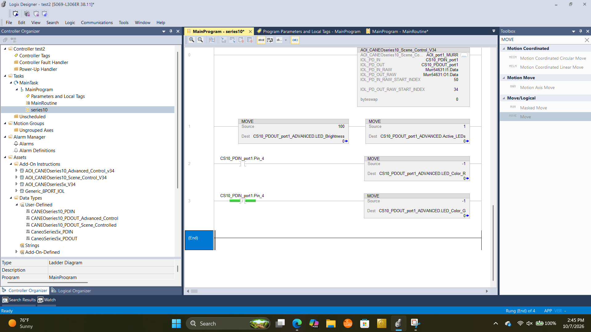
- Rung 0 — calls the AOI. For Advanced control, this must be
AOI_CANEOseries10_Advanced_Control_v34withCS10_PDOUT_port1_ADVANCEDasIOL_PD_OUT. Leave it unconditional. - Rung 1 — sets
LED_Brightnessto100andActive_LEDsto1(LED on). - Rung 2 — while the OUT pin is on (
XIC CS10_PDIN_port1.Pin_4), setsLED_Color_Rto-1(255). - Rung 3 — while the OUT pin is off (
XIO CS10_PDIN_port1.Pin_4), setsLED_Color_Gto-1(255).
Clear the other color when you switch. A
MOVEonly writes while its rung is true, so a color you set stays set until something writes over it. To switch cleanly between red and green, alsoMOVE 0intoLED_Color_Gin rung 2 and intoLED_Color_Rin rung 3. Otherwise both stay at255after the first press and the LED shows yellow.
To blink or pulse the LED, write 1 (Flash Ring) or 2 (Pulse Ring) to LED_Effect and a speed to Effect_Frequency.
9. Using integer arrays and an IO-Link master AOI
Some IO-Link masters, such as the IFM AL1322, import their data as an INT array instead of a SINT array, and some come with their own AOI that pulls one port's data into a separate array. The CANEO series10 AOIs expect SINT arrays, so convert with a CPS instruction on the way in and back on the way out:
- The master manufacturer's AOI (if any) extracts the port's data into its own array.
CPScopies the input array into aSINTarray forIOL_PD_IN_RAW.- The CANEO series10 AOI runs, with both start indexes set to
0because the arrays already hold only that port's data. CPScopies theSINTarray fromIOL_PD_OUT_RAWback into the master's output array.
Set byteswap to 1 for masters that swap bytes, such as IFM. For a full walkthrough with screenshots, see step 7 of the CANEO series5x + Allen-Bradley guide. The same steps apply to the series10.
Tested IO-Link masters
The AOIs were created and tested with the following IO-Link masters:
- MURR IMPACT67 Pro E DIO8 IOL8 M12L 5P (54631)
- IFM AL1322 (byte swap enabled — see step 9)
- SICK SIG300
Other IO-Link masters on EtherNet/IP should work as long as you set the correct start indexes and byteswap value for that master.
Reference
- CANEO series10 Process Data: series10 Process Data
- CANEO series10 LED Control: series10 LED Control
- CANEO series10 LED Scenes: series10 LED Scenes
Download: Add-On Instructions
Download the CAPTRON Add-On Instructions used in this guide. The zip contains both AOIs — CANEOseries10_Scene_Control_V34_AOI.L5X and CANEOseries10_Advanced_Control_v34_AOI.L5X — and each one includes its data types. Unzip it and import the .L5X file you need as described in step 1.